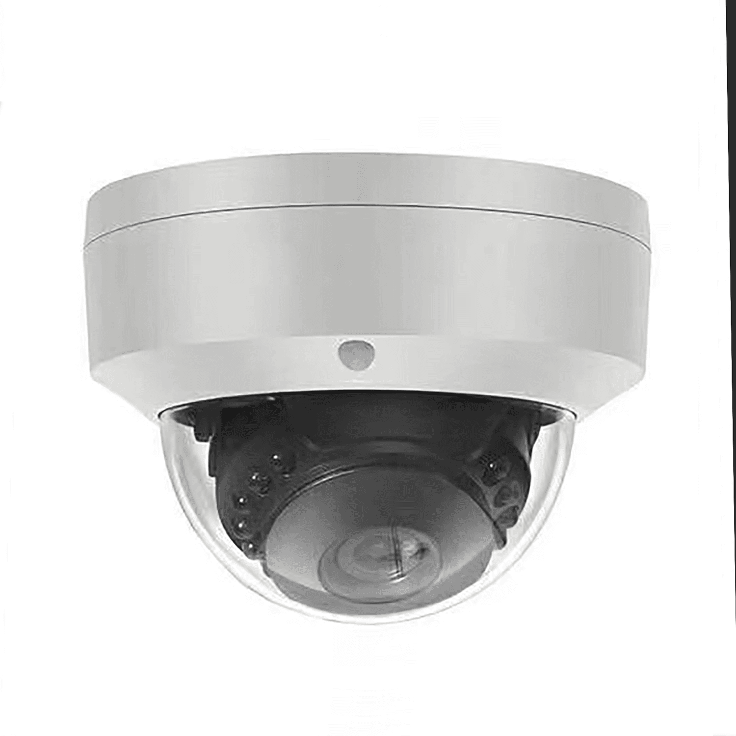
PoE dome cameras with an IP67 metal-and-plastic housing for indoor and outdoor fixed monitoring positions. The JBE-01V housing has a 2.5-inch size specification and 15 IR LEDs.
Model
JBE-01V series
Resolution
2MP / 4MP / 5MP / 8MP configurations
Samples: Paid samples; lead time 7 days.
Standard orders: MOQ 100 units.
OEM orders: MOQ 200 units for logo and label customization.
IP67 metal-and-plastic vandal-resistant dome housing; 2.5-inch housing specification; 15 IR LEDs. Standard 3.6mm fixed lens with 2.8mm and 6mm options. PoE power. Indoor and outdoor use.
Included: screw pack, mounting base and waterproof connector. Recorder and Ethernet cables sold separately.
H.264/H.265 encoding, microphone support, and human and vehicle detection are listed for these configurations. Resolution, sensor, frame rate and processing platform are specified separately for each model below.
Supports ONVIF connectivity. Confirm compatibility with the intended recorder or VMS and the required functions before deployment.
Sensor, resolution, frame rate and hardware platform are configuration-specific. Select a model above or compare the existing configurations below.
All ports show functional connections only, not the rear-panel positions of any specific model. Check the selected camera, recorder, switch and power specifications before installation.
1. Direct Connection to a PoE NVR
Connect each compatible PoE camera to a camera PoE port on the PoE NVR using an Ethernet cable.
Connect the NVR LAN port to the router or local network. Connect a local monitor to the NVR HDMI output.
Connect the specified NVR power supply. Check the PoE standard, per-port power and total power budget for the selected cameras.
Configure and verify local recording. Internet access and the supported remote-access setup are required for viewing from outside the local network.
2. Connection via a PoE Switch
Connect compatible PoE cameras to the PoE switch. A non-PoE IP camera needs its own specified power supply and an Ethernet data connection to the LAN.
Connect the switch uplink to the router or LAN and connect the NVR LAN port to that same network. Follow the selected equipment documentation for the network topology.
Power the NVR and PoE switch separately using their specified supplies. Connect the NVR HDMI output to a local monitor.
Add compatible cameras to the NVR and verify recording. Confirm addressing, supported protocols, recording channels and the PoE power budget before installation.
Local recording and viewing on the connected monitor do not require internet. Remote viewing requires internet access and a supported, correctly configured remote-access method.
Ethernet Waterproof Connector Assembly
Follow these steps to assemble the waterproof cover around the camera’s Ethernet connection.
Prepare the cable
Slide the locking cap, rubber cable seal and waterproof housing onto the Ethernet cable before terminating the RJ45 plug.
Connect and seal
Terminate the RJ45 plug, make sure the O-ring is correctly seated on the camera connector, and insert the plug into the camera’s network socket.
Secure the assembly
Attach the waterproof housing to the camera connector, position the rubber cable seal and tighten the locking cap securely.
Assembly details may vary by connector kit. Follow the instructions supplied with your camera.